|
Please note that year designations might not correspond properly depending on European or US manufacturing models. The AC electronic system consists of several components. The heater controls and IHKA control module AC pressure switch on the drier bottle Some models have a 108C coolant temperatur switch off device The AC lock sensor module AC compressor relay Aux fan relays
The AC lock sensor monitors engine coolant temperature, compressor speed and engine speed. If all is well it allows the AC compressor to get 12 volts applied to enable the system. In this example the control unit is from an V12 750 1989 model, part.no. 61.35.1.390.899(2). 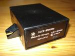 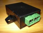
Note! Only 750's have an AC lock sensor! The unit is located on a bracket behind the left kick panel. Remove the kick panel to expose the two bolts that need to be loosened to hook the bracket off the chassis. The bracke also holds the Servotronic (if present) and AC compressor relay (1988 to 1991 models). 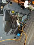 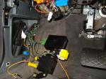
It's either got two green connectors or one bigger green connector. All in all there should be 9 pins if there's two connectors, and 10 pins if there's 1 connector. Not necessarily all are connected though. 1988 750's | Pin | Wire color | Description | | C1-1 | Black / Grey
Blue | To DME's. Signals to increase idle speed when AC is running.
To AC compressor. 12 volts to enable compressor. | | C1-2 | Green / Blue / Yellow | Fuse 29 (12 volts when ignition in start or run) | | C1-3 | Brown / Black | Ground | | C1-4 | Black | DME pin 6. Engine speed signal from coil # 1 | | C1-5 | Brown / Violet | Engine coolant temp.sensor (brown/white) | | C2-1 | Black / Grey | AC compressor speed signal (1 of 2) | | C2-2 | Blue / Brown | AC compressor speed signal (2 of 2) | | C2-3 | Black / Red / Yellow | Low pressure switch* (source of 12 volts for compressor) | | C2-4 | Brown / Yellow | Engine coolant temp.sensor |
*) The other end of the low pressure switch connects to the high pressure switch by a Black / Red wire. It then connects to the AC compressor relay via a Black / Red wire again. When the IHKA grounds pin A8 (Blue / Black wire) it enables the AC compressor relay which the energizes the Black / Red wire from fuse 29 (7.5A). The AC relay is connected to this fuse via two Green / Blue / Yellow wires. If the AC system pressure is correct, a 12 volt should be available at this pin when the AC mode is enable at the heater controls (ign. switch in position II or engine running).
1989 - 90 750's | Pin | Wire color | Description | | C1-1 | Black / Grey
Black / Grey | To DME's. Signals to increase idle speed when AC is running.
To AC compressor. 12 volts to enable compressor. | | C1-2 | Green / Blue / Yellow | Fuse 29 (12 volts when ignition in start or run) | | C1-3 | Brown / Black | Ground | | C1-4 | Black | DME pin 6. Engine speed signal from coil # 1 | | C1-5 | Brown / Violet | Engine coolant temp.sensor (brown/white) | | C2-1 | Blue | AC compressor speed signal (1 of 2) | | C2-2 | Blue / Brown | AC compressor speed signal (2 of 2) | | C2-3 | Black / Red / Yellow | Pressure switch* (source of 12 volts for compressor) | | C2-4 | Brown / Yellow | Engine coolant temp.sensor |
*) The pressure switch is now an integrated 3-way switch in one instead of multiple switches. The other side of the pressure switch is connected to the AC compressor relay via a Black / Red wire. The pressure switch also has two other wires (Black / Grey / Yellow and Brown / Black) that controls the aux fan relay. The AC compressor relay is the source of the AC compressor 12 volt enable signal. It's hooked up to fuse 29 (7.5A) via two Green / Blue / Yellow wires. The IHKA pin A8 (Blue / Black) grounds the AC compressor relay thus enabling 12 volts to pass to the pressure switch, and to the lock sensor if the AC system pressure is correct (ign.switch in position II or engine running).
1991 - 1992 750's | Pin | Wire color | Description | | 1 | Blue | AC compressor speed signal (1 of 2) | | 2 | Brown / Black | Ground | | 3 | Black / Red / Yellow | Low pressure switch* (source of 12 volts for compressor) | | 4 | Green / Blue / Yellow | Fuse 29 (12 volts when ign. in pos. II or engine running) | | 5 | Black / Grey | To AC compressor. 12 volts to enable compressor.
Is also connected to DME to increase idle speed. | | 6 | Blue / Brown | AC compressor speed signal (2 of 2) | | 7 | Brown / Yellow | Engine coolant temp.sensor | | 8 | N/C | | 9 | Brown / Violet | Engine coolant temp.sensor | | 10 | Black | DME and coil. Engine speed. |
*) The pressure switch is now an integrated 3-way switch in one instead of multiple switches. The other side of the pressure switch is connected to the AC compressor relay via a Black / Red wire. The pressure switch also has two other wires (Black / Grey / Yellow and Brown / Black) that controls the aux fan relay. The AC compressor relay is the source of the AC compressor 12 volt enable signal. It's hooked up to fuse 29 (7.5A) via two Green / Blue / Yellow wires. The IHKA pin A8 (Blue / Black) grounds the AC compressor relay thus enabling 12 volts to pass to the pressure switch, and to the lock sensor if the AC system pressure is correct (ign.switch in position II or engine running). 1993 - 1994 750's | Pin | Wire color | Description | | 1 | N/C | | | 2 | Brown / Black | Ground | | 3 | Black / Red / Yellow | Low pressure switch* (source of 12 volts for compressor) | | 4 | Green / Blue / Yellow | Fuse 29 (12 volts when ign. in pos. II or engine running) | | 5 | Black / Grey | To AC compressor. 12 volts to enable compressor.
Is also connected to DME to increase idle speed. | | 6 | N/C | | | 7 | Brown / Yellow | Engine coolant temp. sensor | | 8 | N/C | | 9 | Brown / Violet | Engine coolant temp.sensor | | 10 | Black | DME and coil. Engine speed. |
*) The pressure switch is now an integrated 3-way switch in one instead of multiple switches. The other side of the pressure switch is connected to the AC compressor relay via a Black / Red wire. The pressure switch also has two other wires (Black / Grey / Yellow and Brown / Black) that controls the aux fan relay. The AC compressor relay is the source of the AC compressor 12 volt enable signal. It's hooked up to fuse 29 (7.5A) via two Green / Blue / Yellow wires. The IHKA pin A8 (Blue / Black) grounds the AC compressor relay thus enabling 12 volts to pass to the pressure switch, and to the lock sensor if the AC system pressure is correct (ign.switch in position II or engine running). Opening the unit by carefully pushing away the 4 clips on the side of the casing and pulling the top away from the bottom. 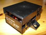
You can then remove the PCB (printed circuit board) from the bottom casing by carefully pushing out near the 4 tabs that hold the PCB in place, and pulling the PCB up and free from the bottom casing. 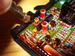
The PCB contains 3 IC's (integrated circuits), a relay, some diodes, transistors, capacitors and resistors. 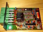 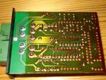
Note! The following is specific to this exact part.no device. Yours may vary. The lower thin one (marked IC2) is not labeled (or covered in black paint). Most likely an A/D converter for the engine coolant temperature. The relay is from Siemens and a V23072-C1061-A208 / BC5MC) model.
|


