|
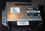
The Transmission Control Module (or Getreibesteurung which it is labeled) is found up under the right kickpanel in the front inside the car. To access it, remove some of the doorlist insulation/gasket where the kickpanel is. Pry out the little cover on top of the kickpanel near the door to reveal the hidden screw behind it. Turn this, and the lower screw 90 degrees either way to open the lock. Note these are of plastic. Open the glovebox and then push the doorlist trim backwards to free the kickpanel tab, and draw the whole kickpanel backwards and out. There is a large tab in front of the kickpanel that locks it to the chassis. Unplug the speakerwirings and remove the kickpanel. Please note that this article specifically deals with an 1991 750iL without adaptive transmission, and a 3-mode select switch in the centerconsole. The pin-out on the computer module, and the wire colors differ somewhat between years and of course choice of 2 or 3-mode select switches and if your car has ASC/ASC+T and the adaptive transmission. The variations are very light so most information found herein should be of some interest for you too. Please check under the Official papers section to find sources of the Bentley Service Manual for the E32. This manual covers all transmissions and wirings. 
The two platic bolts that holds the kickpanel. Upper one hidden under plastic cover.
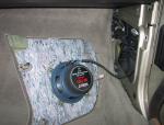
The kickpanel removed revealing speaker and wirings.
With the glovebox open, locate the two black plastic screws that holds the insulation in place. Unscrew these and flip the insulation lightly up and tuck under something to gain free access to the 3 bolts that hold the transmission control unit. 2 bolts on top, and the third one is located under the second one near the door. Loosen these some turns. There is only need to remove the lower left one fully. The other two can just be loosened as the control unit unhooks from the chassis. 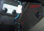
The two platic nuts that holds the insulation in place.
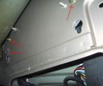
The three bolts that holds the TCM-unit. Only lower left one needs to be fully removed.
To remove the control unit itself, unhook it from the chassis, turn it 90 degrees so that the cables runs downwards to the speaker-hole. Draw the unit carefully out through this hole. You can unclip the electrical connector from the controlunit. There is a metalclip where the wires enter. Push this outward and unhook the connector. You should always disconnect the cars battery before you do this to avoid damage to the unit. 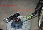
TCM-unit disconnected from it´s 35-pin connector.
Assembly is reverse. Transmission Control Unit pin-out 
35-pin connector
Pin # 1
2
3
4 5
6
7
8 9
10
11
12 13
14
15
16 17
18
19
20 21
22
23
24 25
26
27
28 29
30
31
32 33
34
35 | Wire color Violett
Grey/Yellow
-
Yellow/Green Brown
Brown
-
Brown -
-
White/Black
White/Violett White/Yellow
Yellow/Blue
Yelllow/White
Orange Green
Blue/Black
Brown
Brown/Violett OR Grey Brown/Green
Red
-
Brown/Grey Blue
Blue/Red
White
Black/Brown Blue/White
Brown/White
-
Yellow Grey/Brown
Red
Red/Blue | Wired to Common for Solenoids
EML
Not Used
Mode-switch, Sport Ground
Mode-switch, Ground
Not Used
Speed Sensor line 1/2 -
-
Engine Control System
Computer Dataline Computer Dataline
Mode-switch, Economy
Mode-switch, Manual
Solenoid Valve #1 Solenoid Valve #2
Aut. Position Switch/Inst.Cluster
Ground
- OR Reverse Gear Inhibit Solenoid Engine Control System
Hydraulic Pressure Regulator
Shielding for Speed Sensor lines
Engine Control System Torque Clutch Solenoid
-
Speed Sensor line 2/2
Aut. Pos. Sw/Inst.Cluster/Eng.Ctrl Aut. Position Switch/Inst.Cluster
Aut. Position Switch/Inst.Cluster
-
Not Used Check Control
+B Always
Engine Control System + Relay | Description O: +B ? (16,17,20,22,25)
O: ?
Not Used
I: Ground for Sport I: Grounding
O: Grounding
Not Used
O: Ground?? Not Used
Not Used
O: ?
I: ? I2C-bus? O: +B/pulsing. I2C?
I: Ground for Economy
I: Ground for Manual
O: Ground active? O: Ground active?
I: Ground w/PR21
I: Grounding
O: Ground active? O: ?
O: Ground active?
O: Ground
O: ? O: Ground active?
Not Used
I: Pulse? (see 8)
I: Ground w/PN I: Ground w/N31
I: Ground w/RD
Not Used
Not Used O: +B w/Ign.1+2+Start
I: Always live power
I: +B w/Ign.2+Start |
Pin numbers in bold indicate missing connector pin in my car.
Some theories: 1) Pin 1 is either common +B or Ground for all solenoids in transmission. Not measured. This means the computer controls the solenoids by either grounding or +B´ing each respective line for these (16,17,20,22 and 25). 2) One line to/from the EML. Could this be a failsafe-mode if the engine fails? Meaning the EML signals the transmission computer to go to failsafe in case an EML-fault exists? 3) The speed sensor has two lines and is shielded too. It´s easy to locate as it´s the thick black tubed wiring going to the transmission control unit. I guess one line is either Grounded or put live (+B) and the other then transmits in return pulses as the propeller shaft rotates. It can seem from my measurements that pin 27 is grounded. This in contrary to any logic BMW has, using BROWN for grounded lines. But I suspect my sender to be faulty which would explain this measurement. 4) The Check Control will report TRANS PROGRAM if the TCM is missing. This leads me to suspect that pin 33 (Check Control) is an output line which is grounded by the TCM when everything is A-OK. It is put live when ignition is in either position but off. This could be due to a pull-up resistor on the Check Control input-lines. However this line could be a dataline to signal other faults (TORQUE CONV etc). Further investigation will be needed. 5) The TCM is put into Economy/Sport or Manual by grounding the respective line for the desired function (pin 4,14 and 15). In my car the E/S/M-switch is grounded by another means than from the TCM itself, since pin 6 is not wired. 6) Pin 35 is put live when ignition is in position 2 or 3 (start) (internal relay in TCM is activated when this situation occurs). 7) The automatic position switch is controlled by the user as he/she selects what mode he wants the transmission in (Park, Reverse, Neutral, Drive, 3. gear, 2. gear or 1. gear - PRND321). The below table shows how the TCM reads what position the gear-lever is in. The indicated lines are grounded. The instrument cluster reads these lines too, and displays the correct letter/digit according to them. Gear lever-position
Inst.Cluster displays
P
R
N
D
3
2
1 | Pins grounded on TCM
18 + 25
18 + 30
28 + 29
30
29
18
18 + 29
|
The TCM is based on an Intel B57300 CPU that runs at 8MHz. The software that controls the transmission, upshifts-points, modes and more, is stored on an EPROM.
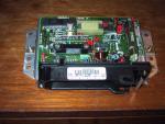
Inside the TCM

Inside the TCM, parts labeled
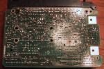
Backside PCB of the TCM
|